

Views: 0 Author: Site Editor Publish Time: 2026-08-06 Origin: Site


High-precision manufacturing requires heavy capital. Yet, the massive gap between expected estimates and actual invoices for custom components constantly wrecks project budgets. Engineering and procurement teams face unpredictable quoting models daily. Minor design choices exponentially inflate manufacturing expenses. Without understanding the underlying cost drivers—like machine time, fixturing, and tolerance demands—teams cannot accurately forecast production expenses or evaluate vendor quotes. We see this on the shop floor all the time. A simple chamfer or an unnecessarily tight tolerance adds hours of setup and runtime. This guide deconstructs the quoting architecture of subtractive manufacturing. We provide a technical framework to evaluate quotes, optimize designs for manufacturability (DFM), and select the right manufacturing partner for scalable production. You will learn exactly where your design bleeds money and how to fix it before sending files to the shop.
Machine Time is the Primary Cost Driver: Hourly rates vary significantly by equipment complexity (e.g., $30–$50/hr for 3-axis vs. $75–$150/hr for 5-axis machines).
Geometry Dictates Setup Costs: Manual part repositioning and custom fixturing required for complex geometries act as severe cost multipliers, often exceeding the cost of the material itself.
Tolerances Must Align with Application: Defaulting to unnecessarily tight tolerances increases scrap rates, requires specialized tooling, and mandates rigorous inspection, directly inflating the per-part price.
Volume Dilutes Setup Expenses: Prototyping carries the highest per-unit cost due to non-recurring engineering (NRE) and setup times, which amortize rapidly as batch sizes increase.
To evaluate a quote accurately, buyers must separate fixed baseline costs from variable, geometry-induced penalties. Understanding how a machine shop calculates your final number allows you to identify where your design is bleeding capital. Estimators do not just guess; they run your CAD model through simulation software to calculate exact material removal rates and setup times.
Estimators rely on a relatively standardized equation to generate quotes. The total cost equals the raw material expense plus the machine time multiplied by the hourly rate, added to the setup or non-recurring engineering (NRE) costs, and finally, any post-processing or finishing requirements. Batch size acts as the primary divisor for setup and NRE costs. This mathematical reality explains the steep price drop between the first unit and the hundredth unit.
Raw Material Procurement: The physical block of metal or plastic required to yield your part, including the extra material needed for workholding.
Programming and Setup (NRE): The time a programmer spends in CAM software generating G-code, plus the physical time an operator spends loading tools, setting work offsets, and machining soft jaws.
Active Machine Runtime: The actual minutes the spindle is turning and cutting material.
Post-Processing and Inspection: Deburring, surface finishing, and quality control measurements.
The time spent programming the toolpaths and physically setting up the workholding is identical whether you make one part or one thousand. When you order a single prototype, that one unit absorbs the entire NRE burden.
The operational cost differences between standard 3-axis milling or turning and advanced 4-axis or 5-axis machining centers are substantial. A standard 3-axis machine handles straightforward geometries where the cutting tool moves along the X, Y, and Z axes. When parts require undercuts or off-axis features, 5-axis machines become necessary. While 5-axis equipment reduces setup time for complex parts by allowing the machine to reach multiple faces without manual repositioning, it carries a significantly higher hourly operational premium due to the machine's initial capital cost and maintenance requirements.
Machine Type | Setup Complexity | Ideal Use Case | Relative Operational Cost |
|---|---|---|---|
3-Axis Mill | High (requires multiple manual flips) | Flat parts, simple brackets, single-sided features | Baseline |
4-Axis Mill | Medium | Cylindrical parts, features on multiple radial faces | Moderate Premium |
5-Axis Mill | Low (often single setup) | Complex aerospace components, impellers, organic shapes | High Premium |
CNC Lathe (Turning) | Low | Symmetrical cylindrical parts, shafts, pins | Baseline |
Engineers often experience sticker shock when upgrading from standard aluminum to stainless steel or titanium. The raw material cost is only part of the equation. The true expense lies in machinability. Hard or abrasive materials slow down feed rates, increase tool wear, and extend total machining time. Machinability ratings dictate the surface feet per minute (SFM) and chip load the cutting tool can handle.
Aluminum 6061 cuts easily at high speeds. The chips evacuate cleanly, and tools last for hundreds of hours. Conversely, 304 stainless steel work-hardens if the tool rubs instead of cuts. Machinists must use rigid setups, specialized carbide tooling, and slower spindle speeds to prevent tool breakage. Titanium 6Al-4V is notoriously difficult, requiring high-pressure coolant systems to manage heat. This extended cycle time directly multiplies the hourly rate of the machine.
Multi-setup operations drastically impact the final quote. Every time a part requires manual repositioning by an operator, labor costs increase and precision risks compound. The physical process takes time. The operator must stop the machine, blow off the chips, unclamp the vise, flip the part, tap it down with a dead blow hammer to ensure it sits flat on the parallels, re-clamp, and often probe the part to set a new work offset (G54). If a part must be flipped three times to machine all sides, the shop must account for three distinct setup phases.
Furthermore, designing parts with organic shapes or non-planar mounting surfaces often requires custom jigs, soft jaws, or specialized workholding. These custom fixtures must be machined out of separate aluminum blocks before your actual part can be produced, adding hidden layers of expense to the NRE line item.
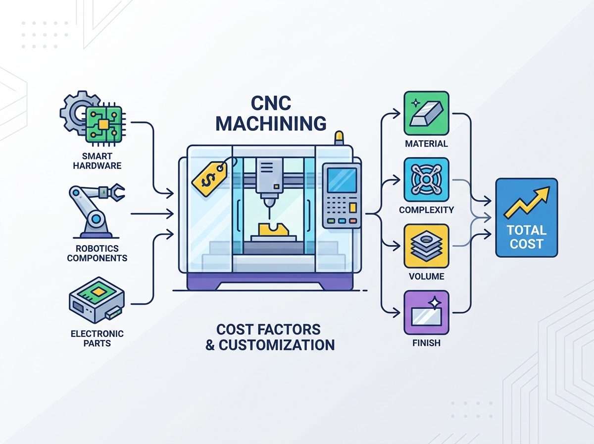
Different sectors require distinct validation, material, and finishing standards that alter the baseline cost structure. Evaluating these requirements early prevents over-engineering and keeps projects within budget constraints.
In robotics components manufacturing, the cost-to-weight ratio is a primary concern. Lightweighting—the process of removing excess material to reduce mass—increases machine time. Pocketing out large sections of a robotic arm or chassis requires extensive roughing and finishing passes. While the final part weighs less, the extended time the machine spends cutting air and material drives up the overall production cost. Engineers must balance the performance gains of a lighter robot against the increased machining hours required to hog out that material.
Thermal management components like heatsinks and enclosures used in electronic parts demand specific surface areas and fin densities. Machining tall, thin cooling fins requires slow feed rates to prevent the fins from bending under cutting forces. If the fins vibrate, they snap the end mill.
For consumer-facing smart hardware parts, cosmetic finishes such as anodizing, bead blasting, or polishing add secondary operational costs. Surface finish requirements dictate smaller step-overs during the machining process. A smaller step-over means the tool must make more passes to achieve a smooth surface before it even reaches the finishing vendor, adding significant runtime.
The amortization of CAM programming and machine setup dictates the financial viability of custom machined parts. In prototyping, the entire NRE burden falls on a single unit. As you move into low-volume production, these fixed costs spread across the batch. Calculating the break-even point where subtractive manufacturing becomes more cost-effective than additive manufacturing depends on the material requirements and the specific geometry. Additive manufacturing often wins for single complex plastic prototypes, but subtractive machining scales better for functional metal components requiring tight tolerances and superior mechanical properties.
Specific CAD features trigger automatic price increases from manufacturing software and human estimators. Recognizing these implementation risks allows teams to optimize designs prior to quoting. A few minutes spent adjusting a CAD model saves thousands of dollars on the shop floor.
The cost curve of precision is exponential. Moving from standard tolerances (±0.005 inches) to tight tolerances (±0.001 inches or tighter) requires slower machining, strict thermal control in the facility, and extensive Coordinate Measuring Machine (CMM) inspection. If a dimension does not interface with a bearing, shaft, or critical mating component, applying a blanket tight tolerance across the entire drawing forces the machinist to treat every feature as critical. This skyrockets the rejection rate and the part price. Machinists have to stop the machine, measure the part manually, adjust tool wear offsets, and run spring passes to hit tight numbers.
End mills have physical limitations. Deep pockets where the depth exceeds four times the width require specialized extended-reach tools. These long tools lack rigidity and are prone to deflection and chatter. To compensate, the machinist must reduce the feed rate and take shallower depth cuts, which increases cycle time and tool breakage risks. Designing shallower cavities or allowing for larger corner radii at the bottom of pockets mitigates this issue, allowing the shop to use standard, rigid tooling.
Excessively thin walls—generally under 0.8mm for metals—lack the rigidity to withstand cutting forces. Machining these features requires multiple light passes to prevent warping and vibration. Harmonics build up when the tool engages a thin wall, causing chatter that destroys the surface finish. The material may also warp after machining due to the release of internal residual stresses. This necessitates specialized workholding, like potting the part in wax, and slower cutting parameters, drastically increasing the time the part spends on the machine.
Specifying a hole diameter of 4.15mm instead of a standard 4.0mm or 4.2mm forces the shop to purchase a custom drill bit or interpolate the hole using a smaller end mill. Interpolation takes significantly longer than a single plunge with a standard drill. Designing around standard fractional or metric tooling sizes for holes and threads eliminates the need for custom tooling purchases and reduces cycle times. Always consult a standard tap drill chart before finalizing hole dimensions.
Sharp internal corners are physically impossible to machine with round rotating tools. Specifying a perfectly square internal corner forces manufacturers to use costly electrical discharge machining (EDM) or extremely small micro-tooling to clear out the remaining material. Adding a radius slightly larger than the standard tool size allows the end mill to glide through the corner without stopping. For example, if you need a pocket machined with a 1/4-inch end mill, specify a corner radius of 0.130 inches instead of 0.125 inches. This prevents the tool from burying itself in the corner and chattering.
Adding machined part numbers, instructions, or logos requires tiny end mills. These fragile tools must run at high RPMs and very slow feed rates to avoid snapping. Machining text can sometimes take longer than machining the structural features of the part itself. Laser engraving or silk-screening are highly cost-effective alternatives that should be applied post-machining. If you must machine text, use raised lettering instead of recessed lettering, as it allows the shop to use larger tools to clear the surrounding material.
Auditing potential vendors requires looking beyond the bottom-line price to understand their operational efficiency and quality control infrastructure. A cheap quote from an unequipped shop ends up costing more in delays and rejected parts.
Instant quoting platforms provide rapid feedback but often result in sticker shock for complex geometries. Automated broker networks excel at speed and standard geometries, routing your part to the shop with open capacity. However, partnering directly with a dedicated CNC machining manufacturer is usually better for complex DFM collaboration, iterative prototyping, and negotiated volume rates. Direct relationships allow for engineering discussions that algorithms cannot facilitate. You can talk to the actual programmer making your part and negotiate design changes to lower the cost.
When evaluating a CNC machining service, assess their machine park age, automation capabilities, and CAM software proficiency. Shops utilizing pallet pools and robotic loading can run lights-out shifts, lowering their overhead and passing those savings onto the buyer. A shop with older equipment may quote a lower hourly rate but take twice as long to machine the part, resulting in a higher final cost. Look for facilities that invest in modern workholding systems like zero-point fixture plates, which drastically reduce setup times between jobs.
Comparing domestic and overseas vendors requires analyzing trade-offs beyond the quoted piece price. Lower overseas labor and machine rates must be weighed against shipping logistics, tariff risks, communication delays across time zones, and intellectual property protection concerns. A cheaper unit price loses its value if shipping delays halt your assembly line or if material certifications are falsified. You must factor in the cost of potential rework and the logistical overhead of managing international freight.
Evaluate the hidden value of ISO 9001, AS9100, or ISO 13485 certifications. A cheaper quote from an uncertified shop often results in higher internal quality assurance costs and rejection rates on your receiving dock. Certified shops maintain calibrated inspection equipment, documented processes, and strict material traceability. They ensure that the parts you receive actually match the CAD files and drawings you submitted, backed by full inspection reports and material test reports (MTRs).
Transitioning from expensive prototypes to cost-optimized production runs requires strategic planning and vendor integration. You cannot simply order larger quantities and expect massive discounts without optimizing the process.
Collaborate directly with your manufacturing partner to strip out unnecessary costs before freezing the design. A thorough DFM review identifies features that require special tooling or extra setups. By adjusting a chamfer, standardizing a thread size, or adding a fixturing tab that can be removed later, engineers can shave significant time off the machining cycle. Good shops will redline your drawings and suggest specific changes to improve tool access and reduce cycle times.
Leverage economies of scale by aligning order quantities with standard material yields and machine shift capacities. Ordering 95 parts might cost the same as ordering 100 if the raw material bar yields 100 units. Setting up blanket orders allows the manufacturer to machine a large batch at once—optimizing their setup costs—and hold the inventory, shipping it to you on a scheduled release basis. This secures volume pricing while managing your cash flow and warehouse space.
Audit your current CAD files to ensure all holes, threads, and internal radii align with standard tooling sizes to eliminate custom tool purchases.
Review all engineering drawings and loosen non-critical tolerances to standard baseline limits, reserving tight tolerances only for critical mating surfaces.
Request itemized quotes from vetted manufacturing partners that clearly break down setup costs, material expenses, and runtime to identify specific cost drivers.
Schedule a DFM review with your chosen vendor before finalizing the design for production to uncover hidden setup complexities.
A: It refers to Computer Numerical Control machining, a subtractive manufacturing process. It works by translating digital CAD models into G-code, which directs automated cutting tools to precisely remove material from a solid block until the desired custom shape is achieved.
A: Hourly rates depend heavily on the equipment and region. Standard 3-axis milling carries a lower baseline hourly rate, while advanced 5-axis machining centers command a premium rate due to higher capital equipment costs, complex maintenance, and the specialized programming skills required to operate them.
A: Low-quantity orders absorb the entirety of Non-Recurring Engineering (NRE) costs. The time required for CAM programming, machine setup, and custom fixturing is fixed. When you order a single prototype, that one unit bears the full cost of the setup phase.
A: You can reduce costs by standardizing internal radii to match common end mills, loosening tolerances on non-critical dimensions, avoiding excessively thin walls, and designing the part to be machined in as few setups as possible.
A: Not always. While the hourly operational rate of a 5-axis machine is higher, it can sometimes be cheaper for complex parts. By allowing the machine to reach multiple sides of the part without manual intervention, it eliminates the labor and time required for multiple setups.
A: Yes. Tough materials like stainless steel or titanium increase costs beyond just the raw material price. They drastically slow down feed rates, extend the total machining cycle time, and wear out cutting tools faster, which directly inflates the final per-part cost.


