

Views: 0 Author: Site Editor Publish Time: 2026-08-04 Origin: Site


Hardware commercialization carries a notoriously high failure rate. The "valley of death" between a conceptual sketch and a mass-manufacturable product often swallows promising projects whole. Friction occurs when aesthetics are prioritized over manufacturability. This misalignment leads to tooling delays, severe cost overruns, and compromised product functionality on the factory floor. Early validation changes this trajectory. A professional industrial design service validates ideas before significant capital is deployed. Testing concepts early mitigates financial risk and prevents late-stage engineering roadblocks that require expensive mold modifications. Partnering with a comprehensive team integrates aesthetic vision with rigorous mechanical engineering, ensuring a seamless transition from initial concept to full-scale production.
Design for Manufacturing (DFM) is Non-Negotiable: A viable industrial design service must evaluate manufacturing constraints during the initial concept phase, not after.
Aesthetic and Structural Alignment: Successful product development requires simultaneous engineering of the overall external contour and the Industrial Internal structure to prevent late-stage redesigns.
Experiential and Functional Balance: Modern hardware must achieve both specific functional requirements and an emotional, experiential connection with the end-user.
Advanced Modeling Accelerates Timelines: Utilizing solid modeling and reverse engineered techniques allows for rapid iteration and precise integration of legacy or off-the-shelf components.
Vendor Evaluation Requires Evidence: Selecting a partner demands scrutinizing their track record of taking products completely through tooling and mass production, not just delivering high-fidelity renders.
Defining the scope of your product development engagement determines the trajectory of your manufacturing success. A full-service engagement encompasses research, ideation, CAD development, prototyping, DFM, and tooling support. Fragmented approaches force you to manage multiple vendors, increasing the risk of miscommunication and data loss between phases. When you separate the aesthetic vision from the mechanical reality, you invite disaster on the factory floor. A unified team bridges the engineering gap. It prevents the "over-the-wall" syndrome where designers hand off unmanufacturable concepts to mechanical engineers. When designers and engineers work concurrently, they resolve conflicts between form and function in real-time. This upfront investment in comprehensive design services drastically reduces long-term capital expenditure on tooling modifications and material waste.
Consider the typical workflow of developing a consumer electronic device. If the design team creates a sleek, ultra-thin enclosure without consulting the mechanical engineers, they might ignore the physical space required for battery expansion or thermal dissipation. The engineers receive the files and immediately realize the product will overheat or the battery will swell and crack the casing. They must then alter the design, adding bulk and ruining the original aesthetic intent. An end-to-end service prevents this. The mechanical constraints inform the initial sketches. The designers know exactly how much internal volume is required before they draw a single line. This concurrent engineering approach saves months of revision time and prevents the costly cycle of redesigning parts that fail preliminary manufacturing checks.
Furthermore, an integrated team understands the realities of injection molding, sheet metal fabrication, and CNC machining. They know that a sharp internal corner will cause stress concentrations and potential part failure. They understand that uneven wall thicknesses will lead to sink marks and warping during the cooling phase of injection molding. By applying these Design for Manufacturing (DFM) principles from day one, the team ensures that the final CAD files are ready for the toolmaker. There is no need for a massive overhaul of the design just to make it manufacturable. The transition from digital model to physical product becomes a predictable, controlled process rather than a chaotic scramble to fix fundamental flaws.
Project Phase | Fragmented Approach Risk | End-to-End Service Advantage |
|---|---|---|
Concept Generation | Concepts ignore factory floor realities, leading to unmanufacturable designs. | DFM constraints guide early sketches, ensuring feasibility from day one. |
Engineering Handoff | Data loss, miscommunication, and complete CAD rebuilds delay the project. | Seamless transition within the same native software environment. |
Prototyping | Prototypes look good but fail functional and assembly testing. | Prototypes validate both aesthetics and mechanical performance simultaneously. |
Tooling Validation | Finger-pointing between design agencies and mold makers over defects. | Unified accountability for T1 sample success and defect resolution. |
The financial implications of this unified approach are massive. Tooling modifications are notoriously expensive. Moving a parting line, adding a slider for an undercut, or changing a draft angle can cost thousands of dollars and add weeks to the schedule. By catching these issues in the digital phase, an end-to-end service eliminates these unexpected expenses. The initial investment in a comprehensive design team pays for itself multiple times over by avoiding tooling rework and ensuring a smooth ramp-up to mass production.
Establishing the visual and emotional identity of a product dictates its market reception. Translating market research and user ergonomics into the initial Product appearance design ensures the hardware achieves the desired experiential impact. Designers map out how users will interact with the device, prioritizing intuitive touchpoints and ergonomic comfort. They study grip angles, button placement, and weight distribution to create a product that feels natural in the hand. This phase is not just about making something look attractive; it is about creating a functional interface between the user and the technology.
Defining the Overall external contour requires strict attention to manufacturing limitations. Designers finalize the outer shell by focusing on parting lines, draft angles, and wall thicknesses required for injection molding. A beautiful surface is useless if it cannot be ejected from a steel mold. Every curve and angle must be evaluated against the direction of pull. If an undercut is necessary for the design, the team must immediately consider the cost and complexity of adding side-actions or lifters to the mold. These decisions cannot be deferred to the engineering phase; they must be integrated into the core aesthetic concept.
Material selection at the appearance design stage impacts perceived value and downstream feasibility. Choosing between ABS, polycarbonate, or a glass-filled nylon changes the structural properties, the surface finish, and the shrinkage rate during molding. The design team must select materials that not only look and feel right but also meet the mechanical requirements of the product. If a device requires high impact resistance, the material choice will dictate the minimum wall thickness, which in turn affects the overall dimensions of the enclosure. The success criteria for this phase is a visually compelling concept that passes preliminary manufacturing feasibility checks.
Color, Material, and Finish (CMF) strategy is another critical component of this phase. The team must define the exact textures, gloss levels, and paint specifications early in the process. Applying a heavy texture to a molded part requires a larger draft angle to prevent the part from sticking to the mold cavity. If the designers specify a deep texture but fail to include the necessary draft, the parts will scuff during ejection, leading to a high scrap rate. By integrating CMF decisions with DFM principles, the team ensures that the final product matches the initial vision without causing headaches on the production line.
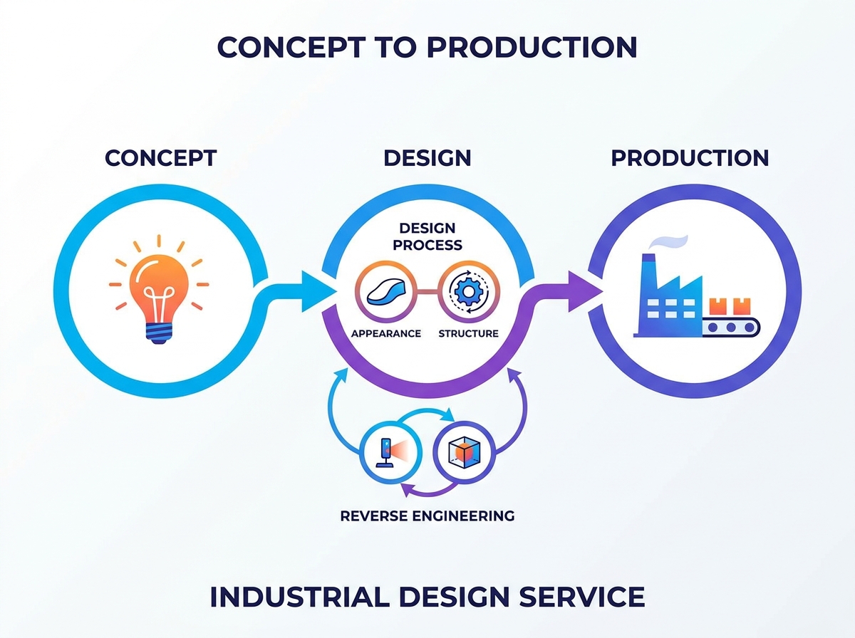
Transitioning from form to function marks the shift from external aesthetics to internal mechanical reality. Developing the Inductrial Internal structure involves housing PCBs, batteries, motors, and wiring harnesses without compromising the approved exterior shell. Engineers must maximize internal volume while maintaining the necessary clearances for assembly. They create mounting bosses, routing channels for wires, and secure battery compartments. Every internal component must be rigidly supported to prevent rattling and ensure long-term reliability. The internal layout must also account for the assembly sequence, ensuring that factory workers can put the device together quickly and without specialized tools.
Mechanical integrity relies on precise structural design. Engineering the overall structure includes integrating ribbing, bosses, snap-fits, and load-bearing elements. These Mechanical structure details ensure durability and compliance with strict drop-test standards. Ribs are added to stiffen large flat surfaces without increasing the overall wall thickness, which would cause sink marks. Bosses are designed with proper gussets to prevent them from breaking off when screws are driven in. Snap-fits are engineered with the correct amount of flex and retention force, allowing for secure assembly without requiring permanent adhesives or ultrasonic welding.
Furthermore, engineers execute tolerance stack-up analysis and thermal management studies. Heat dissipation pathways must be established early to prevent field failures and component degradation. If a device contains a high-power processor or a large battery pack, the engineers must design thermal pads, heat sinks, and ventilation slots to move heat away from sensitive components and the user's hands. They use thermal simulation software to identify hot spots and optimize the internal airflow. Tolerance stack-up analysis ensures that all the individual parts will fit together correctly, even when manufactured at the extremes of their allowable dimensional variations. This rigorous engineering prevents assembly line bottlenecks and reduces the need for manual rework.
The structural phase also involves selecting the appropriate fastening methods. Will the device be held together with machine screws, self-tapping screws, snap-fits, or adhesives? Each method has different implications for assembly time, reworkability, and overall structural integrity. Engineers must balance these factors to create a robust and manufacturable assembly. They must also consider the end-of-life disassembly process, designing the product so that it can be easily taken apart for recycling or repair. This comprehensive approach to mechanical engineering ensures that the product will survive the rigors of daily use and meet all regulatory requirements.
Hardware development often requires interfacing with existing components or legacy systems. When spatial constraints are tight, a reverse engineered approach captures precise mounting points and geometric boundaries. This method guarantees new enclosures fit perfectly around off-the-shelf motors, proprietary circuit boards, or complex mechanical assemblies. Instead of relying on inaccurate manual measurements or outdated 2D drawings, engineers use advanced 3D scanning technology to capture the exact physical dimensions of the existing hardware. This digital replica serves as a highly accurate foundation for the new design.
The technical workflow of Reverse modeling moves from 3D scanning to actionable data. Laser scanners or structured light scanners generate a dense point cloud, capturing millions of data points across the surface of the object. Engineers then use specialized software for surface reconstruction, converting the raw point cloud into a continuous mesh or NURBS surface. This process requires significant skill to filter out noise, fill in missing data, and accurately represent the original geometry. The resulting surface model provides a precise digital envelope that the new design must accommodate.
Transitioning from these surface models to parametric solid modeling ensures the CAD files are fully defined. Editable solid models are mandatory for CNC machining, mold flow analysis, and final production tooling. Unlike a dumb surface model, a parametric solid model contains a history tree of features, allowing engineers to easily modify dimensions, add fillets, or change hole sizes. This flexibility is critical during the iterative design process. The solid model also contains mass properties, allowing engineers to calculate the weight and center of gravity of the final product. By utilizing these advanced digitization techniques, the design team ensures perfect integration between new and existing components, eliminating the risk of interference or misalignment on the assembly line.
This approach is particularly valuable when designing aftermarket accessories or replacement parts. If a company wants to create a custom protective case for a new smartphone, they must reverse engineer the exact contours of the phone to ensure a snug fit. They scan the device, reconstruct the surfaces, and then build the solid model of the case around that digital reference. This guarantees that the camera lenses, buttons, and charging ports align perfectly with the openings in the case. The precision afforded by reverse engineering accelerates the development timeline and significantly reduces the number of physical prototypes required to achieve a perfect fit.
The transition to the factory floor tests the validity of all previous engineering work. The design team plays an active role in shepherding the finalized CAD through the New Product Introduction (NPI) phase. They collaborate directly with toolmakers to approve gate locations, ejector pin placements, and cooling channel layouts. The gate is where the molten plastic enters the mold cavity. Its location affects the flow pattern, the location of weld lines, and the overall cosmetic appearance of the part. The design team must ensure that the gate is placed in an inconspicuous area and that it does not compromise the structural integrity of the component.
Tooling validation centers on evaluating first-off-tool (T1) samples. The team inspects these physical parts to ensure they match the approved design intent. They measure critical dimensions, check for cosmetic defects, and perform preliminary assembly tests. It is rare for T1 samples to be perfect. When unforeseen manufacturing defects arise—such as sink marks, warping, or flash—designers and engineers troubleshoot with contract manufacturers. They analyze the root cause of the defect and determine the most effective corrective action. This might involve adjusting the injection molding process parameters, such as melt temperature or injection pressure, or it might require modifying the tool steel.
Resolving production bottlenecks requires a deep understanding of manufacturing processes. If a part is warping due to uneven cooling, the team might need to add conformal cooling channels to the mold or modify the part geometry to achieve a more uniform wall thickness. If flash is occurring along the parting line, the toolmaker might need to adjust the clamping force or re-machine the mating surfaces of the mold halves. The design team works closely with the factory engineers to implement these changes quickly and efficiently, minimizing delays to the production schedule. They do not simply hand over the CAD files and walk away; they remain actively involved until the manufacturing process is stable and capable of producing high-quality parts consistently.
The NPI phase also involves finalizing the assembly procedures and quality control standards. The design team helps create standard operating procedures (SOPs) for the assembly line workers, ensuring that the product is put together correctly and efficiently. They define the critical inspection points and establish the acceptable tolerances for cosmetic defects. By setting clear expectations and providing detailed documentation, the team ensures that the contract manufacturer can deliver a product that meets the original design intent and satisfies the end-user's expectations. This hands-on approach during the NPI phase is the final, critical step in bringing a hardware product to market successfully.
Selecting the right partner dictates your time to market. You must evaluate their track record of taking products completely through tooling and mass production. Request case studies that show the progression from initial sketches to factory-floor T1 samples. Assess their internal communication protocols between industrial designers and mechanical engineers. A competent partner will immediately ask about your target manufacturing volume, assembly methods, and regulatory compliance requirements during the initial consultation. They will not just show you pretty pictures; they will discuss draft angles, material shrinkage, and assembly tolerances.
Look for a team that has direct experience with your specific manufacturing processes. If you are building a product with complex injection molded parts, you need a partner who understands mold flow analysis and tooling design. If your product involves precision sheet metal fabrication, you need engineers who know how to calculate bend allowances and specify the correct welding techniques. Ask for references from previous clients and inquire about their experience during the NPI phase. Did the design team stay involved during tooling validation? Did they help resolve manufacturing defects? A true partner will take ownership of the final physical product, not just the digital CAD files.
Furthermore, evaluate their capabilities in prototyping and testing. A strong design firm will have in-house 3D printing and CNC machining capabilities to quickly iterate on physical models. They should be able to produce functional prototypes that can be used for user testing and mechanical validation. This rapid prototyping capability is essential for identifying and fixing design flaws before committing to expensive production tooling. By thoroughly vetting your potential partners, you can select a team that has the technical expertise and the practical experience to guide your product from concept to successful mass production.
Audit your current CAD files for basic injection molding constraints, including draft angles and uniform wall thickness.
Request a preliminary DFM report from your design partner before signing off on the final exterior concept.
Establish clear tolerance requirements for all internal components to guide the structural engineering phase.
Schedule a T1 sample review meeting with both your design team and your contract manufacturer to align on quality expectations.
A: The primary goal is to develop a product that meets user needs aesthetically and ergonomically while ensuring it can be manufactured efficiently and reliably at scale.
A: Design for Manufacturing (DFM) should be introduced during the initial concept phase. Evaluating manufacturing constraints early prevents costly redesigns and tooling modifications later in the project.
A: It allows engineers to capture exact dimensions and spatial constraints of existing hardware, ensuring new components or enclosures interface perfectly with legacy parts.
A: Appearance design focuses on the external aesthetics, user touchpoints, and ergonomics. Structural design focuses on the internal mechanical integrity, component mounting, and overall durability.
A: Solid modeling provides a fully defined, mathematically accurate, and editable 3D representation of the part. This data is required for CNC machining, mold flow analysis, and creating injection mold tooling.
A: During New Product Introduction (NPI), finalized designs are transitioned to the factory. This includes tooling creation, process validation, and reviewing initial physical samples to correct any manufacturing defects.


