

Views: 0 Author: Site Editor Publish Time: 2026-08-11 Origin: Site


A successful product launch requires more than a conceptual sketch. It demands a rigorous bridge between user-centric aesthetics and scalable manufacturability. Unlike traditional engineering or fine art, the exact definition of industrial design is often misunderstood. A true industrial design service optimizes function, value, and appearance. It acts as the strategic glue between user experience and mass production.
Many companies invest heavily in design agencies only to receive unmanufacturable art. These concepts look great on screen but fail during engineering, tooling, or compliance testing. This failure leads to severe scope creep and delayed time-to-market. Mitigating this risk requires a clear understanding of what a comprehensive design service actually delivers. This guide deconstructs the specific phases, deliverables, and evaluation criteria necessary to select a partner capable of taking a product from initial concept to mass production.
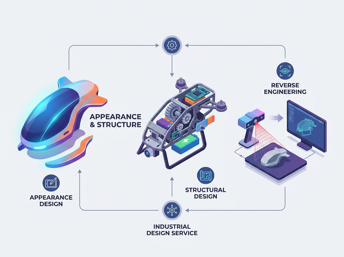
End-to-End Scope: A complete industrial design service encompasses both product appearance design and rigorous mechanical engineering, ensuring the overall external contour aligns seamlessly with the internal components.
Strategic Value Optimization: Beyond aesthetics, top agencies employ design strategists to ensure the product maximizes market value and user satisfaction.
Manufacturability is Non-Negotiable: Viable partners prioritize Design for Manufacturing (DFM) early in the process, preventing costly tooling revisions later.
Advanced Capabilities Matter: Top-tier services utilize reverse modeling and solid modeling to integrate legacy components, benchmark competitors, or optimize existing physical assets.
Clear IP and Deliverables: Successful engagements are defined by transparent intellectual property handoffs and standardized CAD deliverables ready for factory tooling.
Defining the product market fit and commercial viability happens before sketching begins. A design strategist balances user needs, feature sets, and target manufacturing constraints. They map out how the product will function in the real world. This phase sets the foundation for all subsequent engineering work. Deliverables typically include market research reports, user personas, competitive teardowns, and initial product architecture maps. These documents ensure the team builds a product people actually want to use. We often see projects fail because teams skip this step and rush into CAD. Proper strategy aligns the physical form with the actual problem the user faces daily.
During this phase, teams analyze competitor products down to the component level. They tear down existing hardware to understand assembly methods and material choices. This hands-on approach reveals opportunities to reduce part counts or improve ergonomics. A solid strategy phase dictates whether a product needs a ruggedized overmold or a sleek, minimalist enclosure. It establishes the baseline requirements for drop testing, thermal management, and user interface layout.
This phase focuses on the user interface, ergonomics, and aesthetic positioning. Development of the Overall external contour must meet market expectations and brand identity. Designers execute a Color, Material, and Finish (CMF) strategy to balance premium feel with unit constraints. Proper Product appearance design directly influences user interaction and perceived value. Deliverables include 2D concept sketches, high-fidelity 3D renders, and ergonomic study reports. These visual assets help stakeholders approve the general direction before heavy engineering begins.
Ergonomics play a massive role here. If a handheld device causes fatigue after ten minutes of use, the aesthetic appeal does not matter. Designers use physical foam models to test grip angles and button placements. They evaluate how light reflects off different surface textures. A glossy finish might look great in a render but show every fingerprint in reality. Matte textures often hide minor molding defects and provide better grip. The CMF document specifies exact Pantone colors, mold texturing standards (like VDI or Mold-Tech), and secondary operations like pad printing or anodizing.
Transitioning from external aesthetics to functional reality requires deep engineering expertise. Detailed development of the Inductrial Internal structure and overall structure ensures physical integrity. Engineers design the Mechanical structure to include snap-fits, boss features, hinges, and thermal management pathways. Good structural design prevents catastrophic failures during drop testing or daily use. Deliverables include preliminary 3D CAD models, interference checks, and structural simulation reports. This data proves the design will survive manufacturing and assembly.
Engineers must account for material shrinkage during injection molding. They calculate draft angles to ensure parts eject cleanly from the steel tool. Wall thicknesses must remain uniform to prevent sink marks or warping. When designing snap-fits, they calculate the exact strain on the plastic to ensure it flexes without breaking during assembly. Thermal management is another major factor. High-power electronics require carefully designed heat sinks and ventilation pathways to prevent overheating. Finite Element Analysis (FEA) simulates these stresses digitally before any physical parts are made.
Teams utilize 3D scanning and metrology to capture existing physical parts that need to be reverse engineered. Application of Reverse modeling and surface reconstruction translates scanned point-cloud data into editable, parametric CAD files. Creation of precise solid modeling allows for legacy part modernization or competitor benchmarking. Deliverables include reconstructed STEP/IGES files, deviation analysis reports, and optimized parametric models. These files integrate seamlessly into modern manufacturing workflows.
The scanning process uses blue light or laser scanners to capture geometry down to the micron level. However, raw scan data is just a mesh of triangles. It cannot be used for manufacturing. Engineers must rebuild the geometry using NURBS surfaces. They identify the original design intent, correcting any warping or wear present in the physical sample. This reconstructed model serves as the foundation for aftermarket accessories or replacement parts. Deviation analysis compares the new CAD model against the original scan data to verify accuracy.
Establishing the baseline is critical. A concept design is useless if it cannot be molded, stamped, or machined. The provider must deliver native CAD files that include draft angles, wall thicknesses, and parting lines suitable for immediate tooling. You need engineering data, not just pretty pictures. We see many clients burned by agencies that only deliver surface models without any internal fastening strategy.
Deliverable Type | Characteristics | Manufacturing Readiness |
|---|---|---|
Conceptual Design | Focuses on aesthetics, basic form, and user interaction. Often lacks internal details. | Low. Cannot be directly used for tooling or mass production. |
Production-Ready CAD | Includes draft angles, precise tolerances, material specifications, and structural ribs. | High. Ready for injection molding, CNC machining, or sheet metal fabrication. |
Technical Data Package | Contains 2D drawings, BOM, assembly instructions, and CMF callouts. | Complete. Required for factory quotation and quality control. |
Ensure the agency provides a multi-disciplinary team. Move beyond just concept artists. You need mechanical drafters, product designers, and manufacturing liaisons. Collaboration between these roles prevents design flaws from reaching the factory floor. A diverse team catches ergonomic issues and structural weaknesses early. When industrial designers and mechanical engineers work in silos, the result is usually a compromised product. Concurrent engineering ensures the exterior vision aligns with the internal reality.
Lead Industrial Designer: Drives the aesthetic vision and user experience.
Mechanical Engineer: Handles the internal packaging, structural integrity, and DFM.
CMF Specialist: Selects materials and finishes based on cost and durability.
Manufacturing Liaison: Communicates directly with toolmakers to resolve tooling conflicts.
Clarify who owns the design at each milestone. This includes sketches, 3D models, and final engineering files. Ensure the service includes a comprehensive technical data package and Bill of Materials upon project completion. Clear IP handoff protects your investment and allows you to switch manufacturers if necessary. Never accept locked or proprietary file formats. Demand native files (like SolidWorks or Creo) and neutral formats (STEP or IGES).
Recognize that design is not one-size-fits-all. Evaluate if the agency specializes in your specific sector. Consumer electronics require different approaches than medical devices or heavy machinery. Understand how different sectors dictate the approach to structure and user interaction. Sector experience speeds up development and reduces compliance errors. A team experienced in ruggedized industrial equipment knows how to design IP67-rated enclosures. A team focused on medical devices understands ISO 13485 requirements and biocompatible materials.
Evaluate past work for evidence of successful mass production. Visual appeal is not enough. Assess the provider experience with specific manufacturing processes relevant to your product. They must understand injection molding, CNC machining, or sheet metal fabrication. Real-world factory experience is mandatory for a smooth production launch. Ask to see physical samples of their past work. Check for sink marks, flash along parting lines, or mismatched textures. These defects indicate poor DFM practices.
Determine if the design service understands industry-specific compliance. Medical devices need FDA adherence, while electronics require specific IP ratings. Evaluate their ability to scale the design. They must transition smoothly from low-volume prototyping to high-volume offshore manufacturing. Regulatory knowledge prevents costly redesigns late in the development cycle. Designing for UL or CE certification requires specific creepage and clearance distances on internal circuit boards. The mechanical enclosure must accommodate these electrical safety standards.
Analyze how complex surface geometry impacts the cost of injection mold tooling. Intricate external contours often require side-actions or lifters in the mold. Balance the desire for a seamless appearance design with the financial realities of production budgets. Simplifying the exterior can drastically reduce upfront tooling capital. Every undercut adds thousands of dollars to the mold cost. A good designer knows how to achieve a premium look using simple, straight-pull molds.
Weigh the benefits of designing a fully custom mechanical layout against utilizing off-the-shelf internal components. Standard parts accelerate development. Understand how iterative prototyping cycles impact the overall project timeline. Custom engineering takes longer but offers better performance and unique form factors. Using standard batteries, displays, and fasteners reduces supply chain risk. However, a fully custom layout allows for a thinner, more ergonomic final product.
Agencies sometimes silo appearance from structural engineering. This results in beautiful concepts that violate physics or manufacturing constraints. Mandate concurrent engineering where designers and engineers collaborate from day one. Require DFM reviews at every major milestone to catch unmanufacturable features early. If a designer proposes a zero-draft surface on a molded part, the engineer must flag it immediately. Regular design reviews keep the project grounded in reality.
Poor modeling practices lead to tolerance stack-up issues. Prototype parts will fail to assemble correctly. Require the service provider to conduct tolerance analysis. They must manage the initial prototyping phase to validate the design physically. Never sign off on final tooling without a fully functional, tolerance-checked prototype. CNC machined prototypes behave differently than injection-molded parts. The engineering team must account for these material differences during the validation phase.
Compile a detailed Product Requirements Document (PRD) outlining your target user, operating environment, and unit cost constraints.
Request proposals from agencies that explicitly separate conceptual design phases from mechanical engineering and DFM validation.
Demand native CAD files and a complete Technical Data Package (TDP) as part of the final deliverable contract.
Conduct a physical prototype review to verify assembly tolerances and ergonomic feel before authorizing any steel tooling.
A: Appearance design focuses on exterior aesthetics, ergonomics, and user interface. Structural design focuses on internal mechanical engineering, component housing, and manufacturability to ensure the product works and can be built efficiently.
A: These services cover a vast array of physical goods used daily. This includes consumer electronics, medical devices, transportation vehicles, furniture, industrial equipment, and specialized packaging.
A: Costs vary widely based on product complexity, required prototyping iterations, and the extent of DFM engineering needed. Simple consumer goods require less investment than complex electromechanical or medical devices.
A: Reverse modeling digitizes existing physical objects into CAD data. It is essential for designing aftermarket accessories, modernizing legacy parts without original blueprints, or analyzing competitor products for benchmarking.
A: In standard professional service agreements, the client retains full ownership of the IP and all final CAD deliverables once project fees are paid in full. Always verify this clause in your contract.
A: Expect native and neutral 3D CAD files, 2D manufacturing drawings with tolerances, a complete Bill of Materials, CMF specifications, and high-fidelity marketing renders ready for production handoff.
A: A typical end-to-end process takes between 3 to 6 months. This timeline depends heavily on the complexity of the mechanical structure and the number of physical prototyping iterations required for validation.


